About Us
We provide tailored solutions to optimize your heating,ventilation,and air-conditioning needs.
Get a free quote


Suction Line Accumulator


Suction Line Accumulator
The Function of a Suction Line Accumulator in A Heat Pump or Refrigeration System Is to Catch and Hold Any Unused Portion of The System Charge. The Device Must Also Prevent Liquid Slugging of The Compressor and Excessive Refrigerant Dilution of The Compressor Oil.
The Function of a Suction Line Accumulator in A Heat Pump or Refrigeration System Is to Catch and Hold Any Unused Portion of The System Charge. The Device Must Also Prevent Liquid Slugging of The Compressor and Excessive Refrigerant Dilution of The Compressor Oil.
Recommended for: Suction line accumulators are installed in air conditioning and refrigeration systems where sudden return of liquid down the suction line is possible.
A Suction Line Accumulator helps prevent liquid slugging by temporarily storing excess refrigerant and allowing only refrigerant vapor to reach the compressor, ensuring safe and efficient operation of refrigeration and HVAC systems.
-
Designed to protect compressors from liquid refrigerant return.
-
Prevents liquid slugging in refrigeration and HVAC systems.
-
Suitable for both refrigeration and heat pump systems.
-
Compact and robust design for easy installation.
-
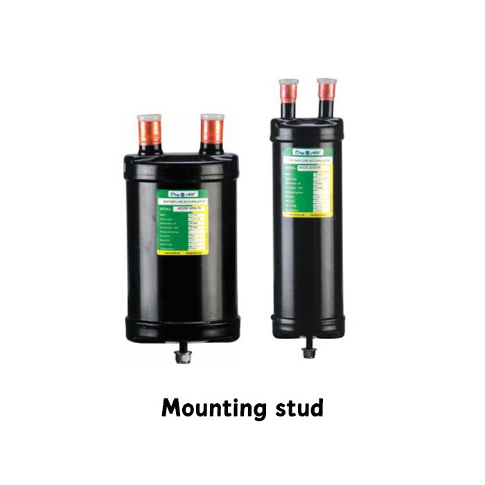
Available with mounting stud or mounting flange options.
-
Models available with integrated heat exchanger for improved efficiency.
-
Designed to handle sudden refrigerant return conditions.
-
Ideal for low temperature and variable load applications.
DIMENSIONAL DATA

| Sr No. | Model | Connection Size (inch) | Dimensions | Mounting Options | Refer Drawing No | |||||||
|---|---|---|---|---|---|---|---|---|---|---|---|---|
| ØA mm | ØA inch | B mm | B inch | C mm | C inch | D mm | D inch | |||||
| SERIES - 3" | ||||||||||||
| 1 | ACC-3185-4S | 1/2" ODF | 76.2 | 3 | 185 | 7.28 | 223 | 8.78 | 41 | 1.65 | M8 X 1.25 PITCH | 1 |
| 2 | ACC-3239-5S | 5/8" ODF | 76.2 | 3 | 239 | 9.41 | 277 | 10.91 | 41 | 1.65 | M8 X 1.25 PITCH | 1 |
| 3 | ACC-3349-6S | 3/4" ODF | 76.2 | 3 | 349 | 13.74 | 387 | 15.24 | 41 | 1.65 | M8 X 1.25 PITCH | 1 |
| 4 | ACC-3370-4S | 1/2" ODF | 76.2 | 3 | 370 | 14.57 | 408 | 16.06 | 41 | 1.65 | M8 X 1.25 PITCH | 1 |
| SERIES - 4" | ||||||||||||
| 5 | ACCF-4254-4S | 1/2" ODF | 101.6 | 4 | 254 | 10 | 290 | 11.41 | 48 | 1.89 | M10 X 1.5 PITCH | 1 |
| 6 | ACCF-4254-5S | 5/8" ODF | 101.6 | 4 | 254 | 10 | 290 | 11.41 | 48 | 1.89 | M10 X 1.5 PITCH | 1 |
| SERIES - 5" | ||||||||||||
| 7 | ACCF-5216-6S | 3/4" ODF | 127 | 5 | 216 | 8.51 | 252 | 9.92 | 70 | 2.76 | M10 X 1.5 PITCH | 2 |
| 8 | ACCF-5216-7S | 7/8" ODF | 127 | 5 | 216 | 8.51 | 253.5 | 9.98 | 70 | 2.76 | M10 X 1.5 PITCH | 2 |
| 9 | ACCF-5330-7S | 7/8" ODF | 127 | 5 | 330 | 12.99 | 367.5 | 14.46 | 70 | 2.76 | M10 X 1.5 PITCH | 2 |
| 10 | ACCF-5330-9S | 1-1/8" ODF | 127 | 5 | 330 | 12.99 | 367.5 | 14.46 | 70 | 2.76 | M10 X 1.5 PITCH | 2 |
| 11 | ACCF-5430-9S | 1-1/8" ODF | 127 | 5 | 430 | 16.93 | 467.5 | 18.41 | 70 | 2.76 | M10 X 1.5 PITCH | 2 |
| 12 | ACCF-5430-11S | 1-3/8" ODF | 127 | 5 | 430 | 16.93 | 467.5 | 18.68 | 70 | 2.76 | M10 X 1.5 PITCH | 2 |
| SERIES - 6" | ||||||||||||
| 13 | ACCF-6330-7S | 7/8" ODF | 152.4 | 6 | 330 | 12.99 | 366.5 | 14.43 | 70 | 2.76 | M10 X 1.5 PITCH | 3 |
| 14 | ACCF-6330-9S | 1-1/8" ODF | 152.4 | 6 | 330 | 12.99 | 366.5 | 14.43 | 70 | 2.76 | M10 X 1.5 PITCH | 3 |
| 15 | ACCF-6430-7S | 7/8" ODF | 152.4 | 6 | 430 | 16.93 | 466.5 | 18.36 | 70 | 2.76 | M10 X 1.5 PITCH | 3 |
| 16 | ACCF-6430-9S | 1'-1/8" ODF | 152.4 | 6 | 430 | 16.93 | 466.5 | 18.36 | 70 | 2.76 | M10 X 1.5 PITCH | 3 |
| 17 | ACCF-6430-11S | 1'-3/8" ODF | 152.4 | 6 | 430 | 16.93 | 473.5 | 18.64 | 70 | 2.76 | M10 X 1.5 PITCH | 3 |
| 18 | ACCF-6430-13S | 1'-5/8" ODF | 152.4 | 6 | 430 | 16.93 | 489 | 19.25 | 70 | 2.76 | M10 X 1.5 PITCH | 3 |
| 19 | ACCM-6508-13S | 1'-5/8" ODF | 152.4 | 6 | 508 | 20 | 567 | 22.32 | 70 | 2.76 | M10 X 1.5 PITCH | 3 |
| 20 | ACCM-6635-13S | 1'-5/8" ODF | 152.4 | 6 | 635 | 25 | 694 | 27.32 | 70 | 2.76 | Round flange | 4 |
| Sr No. | Model | Holding Capacity LBS |
KG | Approx Max Ton R22 AT +40°F |
Connection Size (inch) | Dimensions | Mounting Flange Options | Refer Drawing No | |||||||||
|---|---|---|---|---|---|---|---|---|---|---|---|---|---|---|---|---|---|
| ØA | B | C | D | E | |||||||||||||
| mm | inch | mm | inch | mm | inch | mm | inch | mm | inch | ||||||||
| SERIES - Ø 3" | |||||||||||||||||
| 1 | ACC-3150-3S | 0.50 | 0.5 | 3/8" ODF | 76.2 | 3 | 150 | 5.91 | 187 | 7.36 | 40 | 1.57 | 122.5 | 4.82 | Mounting Flange | 1 | |
| 2 | ACC-3185-4S | 1.6 | 0.74 | 1.02 | 1/2" ODF | 76.2 | 3 | 185 | 7.28 | 223 | 8.78 | 41 | 1.65 | NA | NA | M8 X 1.25 PITCH | 1 |
| 3 | ACC-3239-5S | 2.18 | 0.99 | 2.28 | 5/8" ODF | 76.2 | 3 | 239 | 9.41 | 277 | 10.91 | 41 | 1.65 | NA | NA | M8 X 1.25 PITCH | 1 |
| 4 | ACC-3349-6S | 3.05 | 1.38 | 3.43 | 3/4" ODF | 76.2 | 3 | 349 | 13.74 | 387 | 15.24 | 41 | 1.65 | NA | NA | M8 X 1.25 PITCH | 1 |
| 5 | ACC-3370-4S | 3.27 | 1.48 | 4.04 | 1/2" ODF | 76.2 | 3 | 370 | 14.57 | 408 | 16.06 | 41 | 1.65 | NA | NA | M8 X 1.25 PITCH | 1 |
| SERIES - Ø 4" | |||||||||||||||||
| 6 | ACC-4254-4S | 3.84 | 1.74 | 1.02 | 1/2" ODF | 101.6 | 4 | 254 | 10 | 290 | 11.41 | 48 | 1.89 | NA | NA | M10 X 1.5 PITCH | 1 |
| 7 | ACC-4254-5S | 2.28 | 5/8" ODF | 101.6 | 4 | 254 | 10 | 290 | 11.41 | 48 | 1.89 | NA | NA | M10 X 1.5 PITCH | 1 | ||
| SERIES - Ø 5" | |||||||||||||||||
| 8 | ACC-5216-6S | 3.43 | 3/4" ODF | 127 | 5 | 216 | 8.51 | 252 | 9.92 | NA | NA | NA | NA | M10 X 1.5 PITCH | 1 | ||
| 9 | ACC-5216-7S | 5.45 | 2.46 | 7/8" ODF | 127 | 5 | 216 | 8.51 | 253.5 | 9.98 | 130 | 5.12 | NA | NA | Mounting Flange | 2 | |
| 10 | ACCM-5216-7S | 4.57 | 7/8" ODF | 127 | 5 | 216 | 8.51 | 253.5 | 9.98 | NA | NA | 130 | 5.12 | M10 X 1.5 PITCH | 1 | ||
| 11 | ACC-5330-7S | 7/8" ODF | 127 | 5 | 330 | 12.99 | 367.5 | 14.46 | NA | NA | 130 | 5.12 | Mounting Flange | 2 | |||
| 12 | ACCM-5330-7S | 8.17 | 3.70 | 7/8" ODF | 127 | 5 | 330 | 12.99 | 367.5 | 14.46 | NA | NA | NA | NA | M10 X 1.5 PITCH | 1 | |
| SERIES - Ø 6" | |||||||||||||||||
| 19 | ACC-6330-7S | 4.57 | 7/8" ODF | 152.4 | 6 | 330 | 12.99 | 366.5 | 14.43 | NA | NA | 130 | 5.12 | M10 X 1.5 PITCH | 1 | ||
| 20 | ACCM-6330-7S | 11.99 | 5.43 | 7/8" ODF | 152.4 | 6 | 330 | 12.99 | 366.5 | 14.43 | NA | NA | 130 | 5.12 | M10 X 1.5 PITCH | 2 | |
| SERIES - Ø 8" | |||||||||||||||||
| 31 | ACCM-8350-17S | 24.2 | 11 | 2-1/8" ODF | 219 | 8 | 350 | 13.8 | 427 | 16.8 | 100 | 3.9 | - | - | Mounting Flange | 3 | |
| SERIES - Ø 10" | |||||||||||||||||
| 32 | ACCM-105485-21S | 51.6 | 23.4 | 2-5/8" ODF | 273 | 10 | 485 | 19 | 550 | 21.7 | 127 | 5 | - | - | Mounting Flange | 4 | |
| Diameter | 3 | 4 | 5 | 6 | 8 | 10.5 | |
|---|---|---|---|---|---|---|---|
| Connection Size | NO | Model ACC | |||||
| 3/8" | 3 | 150 | 254 | ||||
| Type | S | S | |||||
| 1/2" | 4 | 185 / 370 | 254 | ||||
| Type | S | S | |||||
| 5/8" | 5 | 239 | |||||
| Type | S | ||||||
| 3/4" | 6 | 349 | 216 | ||||
| Type | S | S | |||||
| 7/8" | 7 | 216 / 330 | 330 / 430 | ||||
| Type | S | S | |||||
| 1-1/8" | 9 | 330 / 430 | 330 / 430 | ||||
| Type | S | S | |||||
| 1-3/8" | 11 | 430 | 430 | ||||
| Type | S | S | |||||
| 1-5/8" | 13 | 430 | 350 | ||||
| Type | S | S | |||||
| 2-1/8" | 17 | ||||||
| Type | |||||||
| 2-5/8" | 21 | 485 | |||||
| Type | S | ||||||
FAQ: ‘Dry All’ Suction Line Accumulators
Why a Suction Line Accumulator (Accumulator) is required in HVAC&R System?
A compressor is designed to compress vapour and not liquid refrigerant. There are many scenarios where liquid refrigerant may enter the compressor and damage it. The Suction Line Accumulator (Accumulator) can really help system win this battle by ensuring only vapour refrigerant will enter the compressor. Accumulator prevents sudden surge of liquid refrigerant that could enter the compressor from the suction line. Accumulator is a temporary reservoir for vapour & liquid refrigerant and oil.
How does an Accumulator work and serve the purpose?
Accumulator is usually a vertical vessel with inlet and outlet connections at top. Due to density difference during cycle operation, liquid refrigerant is accumulated at the bottom of the Accumulator and remaining volume is occupied by the vapor refrigerant.
It has a free-flowing inlet for refrigerant to enter from the Suction line. The outlet is through a ‘U’ Tube. The ‘U’ tube inlet is at the top, with the bend going upto the bottom and connected to the outlet tube.
This U-tube design helps to draw gaseous refrigerant off the top of the vessel. At the bottom of the U-tube, an orifice picks up a small amount of oil and meters it back with the gaseous refrigerant. The small amount of liquid refrigerant will boil off in the suction line. The oil will be carried with the gaseous refrigerant back to the compressors.
Where is Accumulator installed in HVAC&R system?
The Suction Line Accumulators must be installed in a vertical position, after the Evaporator and as close possible to the Compressor and at the same level as compressor.
On systems with a reversing valve and on heat pump systems, the accumulator should be installed between the compressor and the reversing valve.
What are the different types of Accumulator available in Dry All product range?
Dry All offers both Vertical and Horizontal type Accumulators. But Horizontal Accumulator are available only as customized model on customer request.
How Can I Become A Member?
It is a long established fact that a reader will be distracted by the readable content of a page when looking at its layout. The point of using Lorem Ipsum is that it has...
How do you select an Accumulator Model?
Accumulator should be on basis of the following parameters:
- If system is using TXV, holding capacity should be minimum 50% of total refrigerant charge of the System.
- If System with Capillary tube, holding capacity should be minimum 70% of total refrigerant charge of the System.
- The inlet and outlet connection should be same as or larger than Suction line size of the system.
- Note: The volume should never be below 50% of the refrigerant charge.
- Do not choose Accumulator based on the connection sizes only.
In what capacity range are Dry All Accumulators available?
Dry All Accumulators off-the-shelf models are available from 0.5 Litre – 35 Litre capacity.
What is the Maximum allowable pressure / Maximum Working Pressure of Dry All Accumulators?
We have Accumulators available with MWP ranging from 25 bar–31 bar. Please check with us for more information.
Are Dry All Accumulators UL Listed
Yes, certain range of Dry All Accumulators are UL listed. The UL File number is SA45127-20181127
What are types of mounting / Fixing available in Dry All Accumulators?
Two type of mountings are available:
- a) Bolted & Nut (Stud type)
- b) Mounting Flange
Does Dry All make customized Accumulators?
Yes, we make customized Accumulators as per customer design and specification. Please contact Dry All for more details on the process, models available, MOQ, Price, etc.
Does Dry All Accumulators have in built Fusible Plug / Pressure Relief Valve?
All models above 3” Diameter & UL listed has inbuilt fusible plugs.
Do we need to install Suction Line Filter Driers before the Accumulator?
We strongly recommend to install Suction Line Filter Drier / Suction Line Filter before the Accumulator. This prevents the oil pickup orifice in the accumulators from clogging in case the system oil is carrying wax or other debris.